一、简单的VLAN实验
设PC1和PC3都是VLAN13,PC2和PC4属于VLAN24,实现同一个VLAN的设备可以互通。
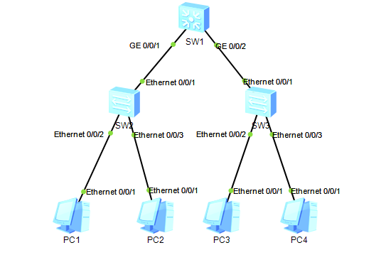
配置概述
1. 交换机:在SW1~3都创建2个vlan;
2. 交换机-交换机:在交换机之间的连接接口配置中继,并且放行相应的VLAN;
3. 交换机-PC:在交换机与PC连接的接口配置Access接口,并且方通相应的VLAN;
4. PC:配置对于VLAN的IP。
SW1
#
system-view
sysname SW1
vlan batch 13 24
display vlan
#
interface GigabitEthernet 0/0/1
port link-type trunk
port trunk allow-pass vlan 13 24
quit
interface GigabitEthernet 0/0/2
port link-type trunk
port trunk allow-pass vlan 13 24
#
display port vlan
#
SW2
#
system-view
sysname SW2
vlan batch 13 24
display vlan
#
interface Ethernet 0/0/1
port link-type trunk
port trunk allow-pass vlan 13 24
quit
display port vlan
#
interface Ethernet 0/0/2
port link-type access
port default vlan 13
stp edged-port enable
interface Ethernet 0/0/3
port link-type access
port default vlan 24
stp edged-port enable
quit
display port vlan
SW3
#
system-view
sysname SW3
vlan batch 13 24
display vlan
#
interface Ethernet 0/0/1
port link-type trunk
port trunk allow-pass vlan 13 24
quit
display port vlan
#
interface Ethernet 0/0/2
port link-type access
port default vlan 13
stp edged-port enable
interface Ethernet 0/0/3
port link-type access
port default vlan 24
stp edged-port enable
quit
display port vlan
实验验证
# PC1 ping PC3
ping 13.1.1.3
# PC2 ping PC4
ping 24.1.1.4
二、简单的静态路由实验
配置静态路由,是LoopbBack 0之间可以Ping通。
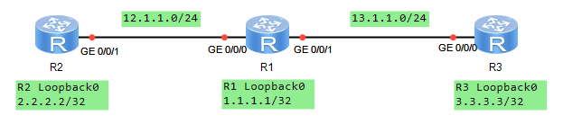
配置概述
1. 给设备命名
2. 配置路由器之间的接口IP地址
3. 添加静态路由
4. 测试Loopback0口之间的网络
R1
#
system-view
sysname R1
#
interface GigabitEthernet 0/0/0
ip address 12.1.1.1 255.255.255.0
quit
#
interface GigabitEthernet 0/0/1
ip address 13.1.1.1 255.255.255.0
quit
#
interface LoopBack 0
ip address 1.1.1.1 255.255.255.255
quit
#
display ip interface brief
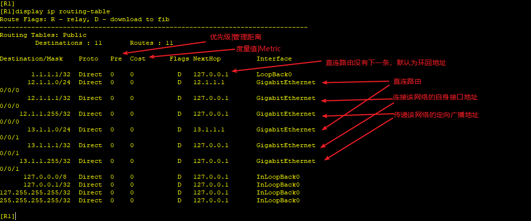
display ip routing-table
#
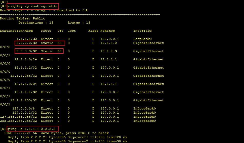
ip route-static 2.2.2.2 32 GigabitEthernet 0/0/0 12.1.1.2
ip route-static 3.3.3.3 32 GigabitEthernet 0/0/1 13.1.1.3
display ip routing-tableR2
#
system-view
sysname R2
#
interface GigabitEthernet 0/0/1
ip address 12.1.1.2 255.255.255.0
quit
#
interface LoopBack 0
ip address 2.2.2.2 255.255.255.255
quit
#
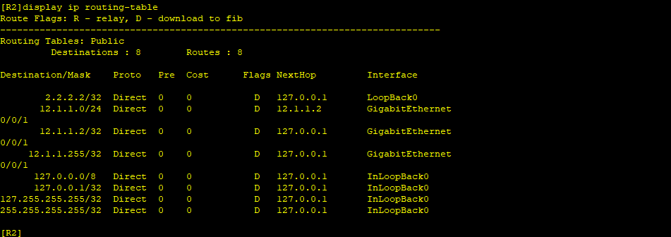
display ip interface brief
display ip routing-table
#
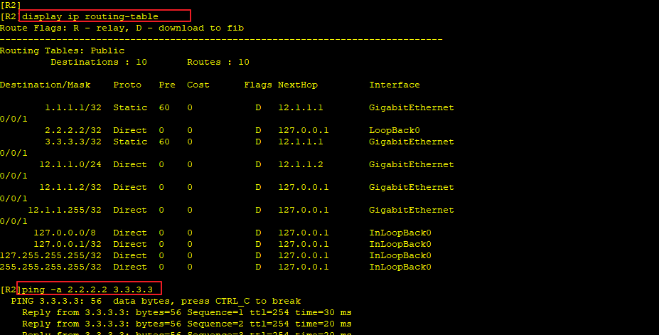
ip route-static 1.1.1.1 32 GigabitEthernet 0/0/1 12.1.1.1
ip route-static 3.3.3.3 32 GigabitEthernet 0/0/1 12.1.1.1
display ip routing-tableR3
#
system-view
sysname R3
#
interface GigabitEthernet 0/0/0
ip address 13.1.1.3 255.255.255.0
quit
#
interface LoopBack 0
ip address 3.3.3.3 255.255.255.255
quit
#
display ip interface brief
display ip routing-table
#
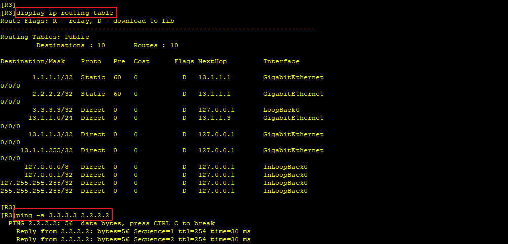
ip route-static 1.1.1.1 32 GigabitEthernet 0/0/0 13.1.1.1
ip route-static 2.2.2.2 32 GigabitEthernet 0/0/0 13.1.1.1
display ip routing-table查看路由信息
配置动态路由之前直连路由信息
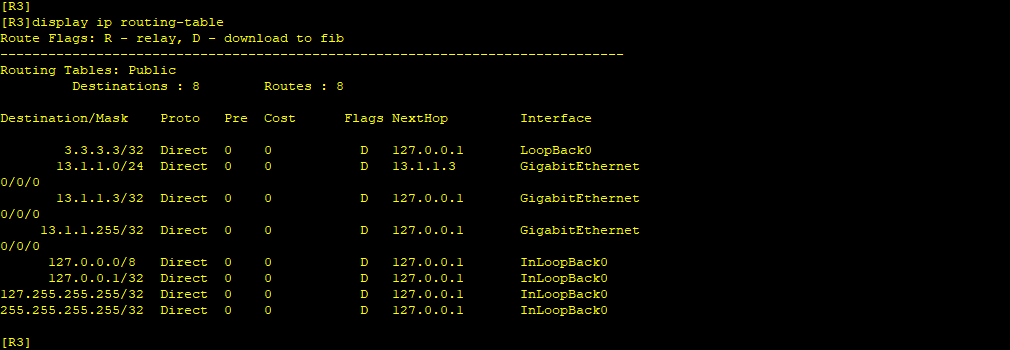
配置动态路由之后的路由信息
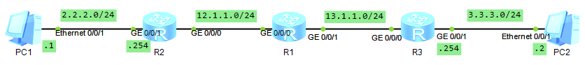
三、简单的OSPF实验
使用OSPF协议使PC1和PC2互通。
配置概述
1. 路由器启用OSPF进程
2. 设置路由器ID
3. 路由器之间的直连接口宣告到同一个区域
4. 路由器与非路由的接口也需要宣告一个区域
R1
#
system-view
sysname R1
#
interface GigabitEthernet 0/0/0
ip address 12.1.1.1 255.255.255.0
quit
#
interface GigabitEthernet 0/0/1
ip address 13.1.1.1 255.255.255.0
quit
#
display ip interface brief
#
ospf 10 router-id 1.1.1.1
area 0
network 12.1.1.1 0.0.0.0
network 13.1.1.1 0.0.0.0
quit
#
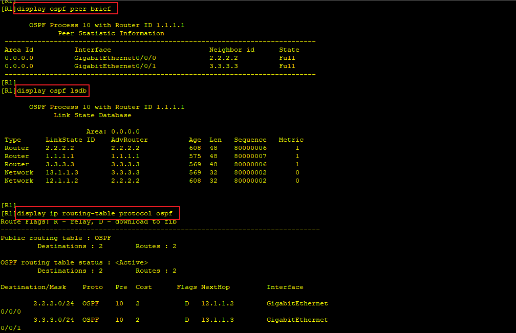
display ospf peer brief
display ospf lsdb
display ip routing-table protocol ospf
# R2
#
system-view
sysname R2
#
interface GigabitEthernet 0/0/0
ip address 12.1.1.2 255.255.255.0
quit
#
interface GigabitEthernet 0/0/1
ip address 2.2.2.254 255.255.255.0
quit
#
display ip interface brief
#
ospf 10 router-id 2.2.2.2
area 0
network 2.2.2.254 0.0.0.0
quit
#
interface GigabitEthernet 0/0/0
ospf enable 10 area 0
quit
#
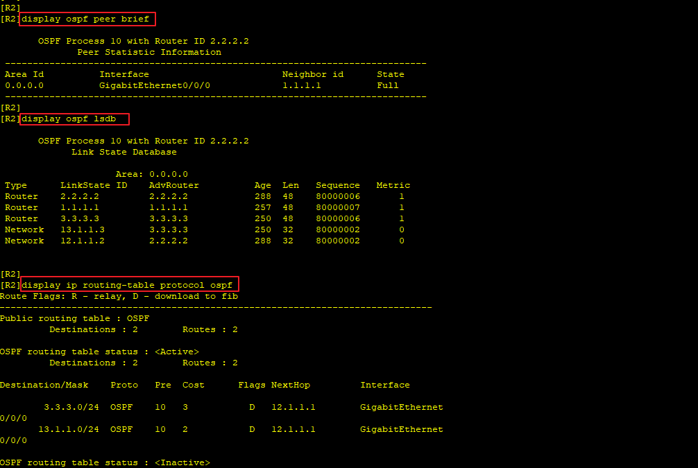
display ospf peer brief
display ospf lsdb
display ip routing-table protocol ospf
# R3
#
system-view
sysname R3
#
interface GigabitEthernet 0/0/0
ip address 13.1.1.3 255.255.255.0
quit
#
interface GigabitEthernet 0/0/1
ip address 3.3.3.254 255.255.255.0
quit
#
display ip interface brief
#
ospf 10 router-id 3.3.3.3
area 0
network 13.1.1.3 0.0.0.0
network 3.3.3.254 0.0.0.0
quit
#
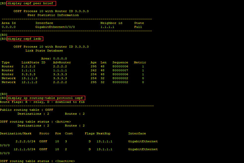
display ospf peer brief
display ospf lsdb
display ip routing-table protocol ospf
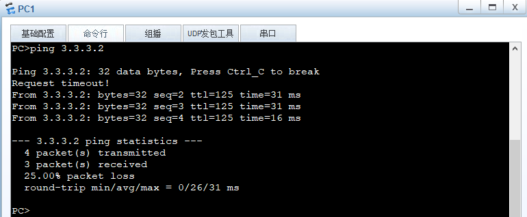
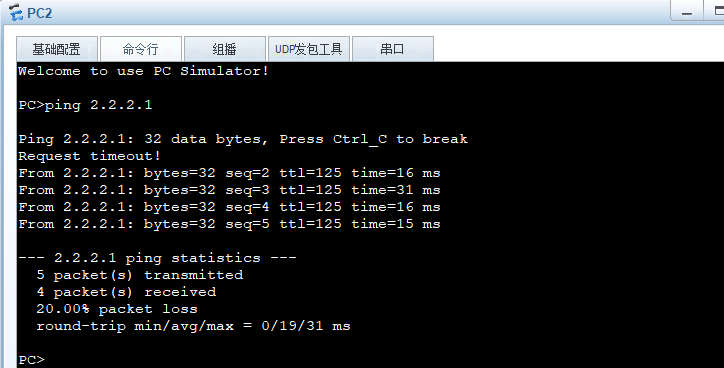
# 测试验证
Templet、实验模板
实验概述。
实验拓扑
配置概述
1.R1
#
system-view
sysname R1
测试验证
转载请注明来源,欢迎对文章中的引用来源进行考证,欢迎指出任何有错误或不够清晰的表达。可以邮件至 hjxstart@126.com
